
IP Services
The IP Services section of the ADC allows you to add, delete and configure the various virtual IP services you need for your particular use case. The settings and options fall into the sections below. These sections are on the right side of the application screen.
Virtual Services
A Virtual Service combines a Virtual IP (VIP) and a TCP/UDP port on which the ADC listens. Traffic arriving at the Virtual Service IP is redirected to one of the Real Servers associated with that service. The Virtual Service IP address cannot be the same as the management address of the ADC. i.e. eth0, eth1 etc…
The ADC determines how the traffic is re-distributed to the Servers based on a load balancing policy set within the Basic tab in the Real Servers section.
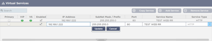
Creating a new Virtual Service using a new VIP
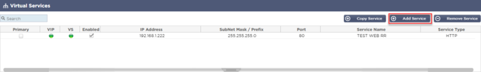
· Click the Add Virtual Service button as indicated above.
· You will then enter the edit row mode.
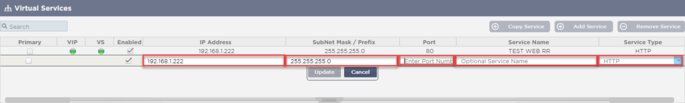
· Complete the four highlighted fields to proceed, and then click the update button.
Please use the TAB key to navigate through the fields.
|
Field
|
Description
|
|
IP Address
|
Enter a new Virtual IP address to be the target entry point for accessing the Real Server. This IP is where users or applications will point to access the load-balanced application.
|
|
Subnet Mask/Prefix
|
This field is for the subnet mask relevant to the network on which the ADC sits
|
|
Port
|
The entry port used when accessing the VIP. This value does not necessarily need to be the same as the Real Server if you use Reverse Proxy.
|
|
Service Name
|
The service name is a textual representation of the VIP’s purpose. It is optional, but we recommend you provide this for clarity.
|
|
Service Type
|
There are many different Service Types available for you to select. Layer 4 service types cannot use flightPATH technology.
|
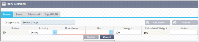
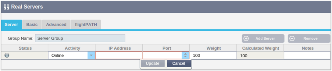
You can now press the Update button to save this section and jump automatically to the Real Server section detailed below:
|
Field
|
Description
|
|
Activity
|
The Activity field can be used to show and change the status of the load-balanced real server.
Online – Denotes that the server is active and receiving load-balanced requests
Offline – The server is offline and is not receiving requests
Drain – The server has been placed in drain mode so that persistence can flush and the server moved to an offline state without affecting users.
Standby – The server has been placed in a standby state
|
|
IP Address
|
This value is the IP address of the Real Server. It must be accurate and should not be a DHCP address.
|
|
Port
|
The target Port of access on the Real Server. When using a reverse proxy, this can be different from the entry Port specified on the VIP.
|
|
Weighting
|
This setting usually is automatically configured by the ADC. You can change this if you wish to change the priority weighting.
|
· The Status light will first turn Grey, followed by Green should the Server Health Check succeed. It will turn Red if the Real Server Monitor fails.
· A server that has a red status light will not be load balanced.
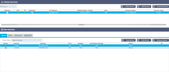
Example of a completed Virtual service
Create a new Virtual Service using an existing VIP
· Highlight a Virtual Service you wish to copy
· Click Add Virtual Service to enter row edit mode
· The IP Address and Subnet Mask copies across automatically
· Enter the Port Number for your service
· Enter an optional Service Name
· Select a Service Type
· You can now press the Update button to save this section and jump automatically to the Real Server section below
· Leave the server Activity option as Online – this means it will be load balanced if it passes the default health monitor of TCP Connect. This setting can be changed later if required.
· Enter an IP address of the Real Server
· Enter a Port Number for the Real Server
· Enter an optional name for the Real Server
· Click Update to save your changes
· The Status light will first turn Grey, then Green if the Server Health Check succeeds. It will turn Red if the Real Server Monitor fails.
· A server that has a Red Status light will not be load balanced
Changing the IP Address of a Virtual Service
You can change the IP address of an existing Virtual Service or VIP at any time.
· Highlight the Virtual Service whose IP address you wish to change
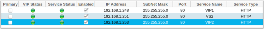
· Double click the IP address field for that service
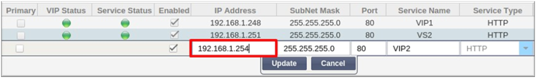
· Change the IP address to the one you wish to use
· Click the Update button to save the changes.
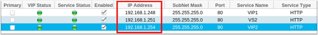
Note: Changing the IP address of a Virtual Service will change the IP address of all services associated with the VIP
Creating a new Virtual Service using Copy Service
· The Copy Service button will copy an entire service, including all the Real Servers, basic settings, advanced settings, and flightPATH rules associated with it
· Highlight the service you wish to duplicate and click Copy Service
· The row editor will appear with the blinking cursor on the IP Address column
· You must change the IP address to be unique, or if you wish to keep the IP address, you must edit the Port so it is unique to that IP address
Don't forget to edit each tab if you change a setting such as a load balancing policy, the Real Server monitor, or remove a flightPATH rule.
Filtering displayed data
Searching for a specific term
The Search box allows you to search the table using any value, such as the octets of the IP address or name of the service.
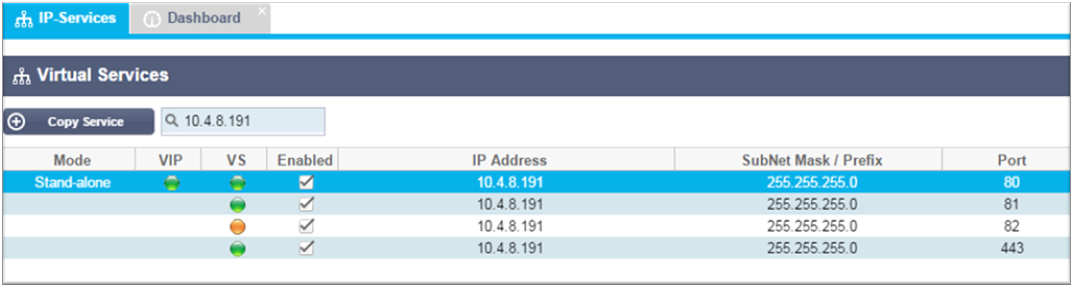
The example above shows the result of searching for a specific IP address of 10.4.8.191.
Selecting column visibility
You can also select the columns that you wish to display in the dashboard.
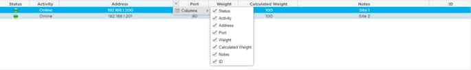
· Move the mouse over any one of the columns
· You will see a small arrow appear on the right side of the column
· Clicking the checkboxes selects the columns you wish to see in the dashboard.
Understanding the Virtual Services columns
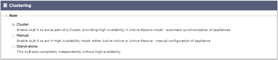
Primary/Mode
The Primary/Mode column indicates the high availability role selected for the current VIP. Use the options available in System > Clustering to configure this option.
|
Option
|
Description
|
|
Cluster
|
Cluster is the default role for the ADC at installation, and the Primary/Mode column will indicate the mode it is currently running in. When you have an HA pair of ADC appliances in your datacentre, one of them will show Active and the other Passive
|
|
Manual
|
The Manual role allows the ADC pair to run in Active-Active mode for different Virtual IP addresses. In such cases, the Primary column will contain a box next to each unique Virtual IP that is tickable for Active or left un-ticked for Passive.
|
|
Stand-Alone
|
The ADC is acting as a stand-alone device and is not in High Availability mode. As such, the Primary column will state Stand-alone.
|
VIP
This column provides visual feedback on the status of each Virtual Service. The indicators are color-coded and are as follows:
|
LED
|
Meaning
|
|
l
|
Online
|
|
l
|
Failover-Standby. This virtual service is hot-standby
|
|
l
|
Indicates a "secondary" is holding off for a "primary."
|
|
l
|
Service Needs attention. This indication may result from a Real Server failing a health monitor check or has been changed manually to Offline. Traffic will continue to flow but with reduced Real Server capacity
|
|
l
|
Offline. Content servers are unreachable, or no content servers enabled
|
|
l
|
Finding status
|
|
l
|
Not licensed or licensed Virtual IPs exceeded
|
Enabled
The default for this option is Enabled, and the checkbox shows as ticked. You can disable the Virtual Service by double-clicking the line, unticking the checkbox, and then clicking the Update button.
IP Address
Add your IPv4 address in decimal dotted notation or an IPv6 address. This value is the Virtual IP address (VIP) for your service. Example IPv4 "192.168.1.100". Example Ipv6 “2001:0db8:85a3:0000:0000:8a2e:0370:7334”
Subnet Mask/Prefix
Add your subnet mask in decimal dotted notation. Example "255.255.255.0". Or for IPv6, add in your Prefix. For more information about IPv6, please see HTTPs://en.wikipedia.org/wiki/IPv6_address
Port
Add the port number associated with your service. The port can be a TCP or UDP port number. Example TCP "80" for Web Traffic and TCP "443" for Secured Web Traffic.
Service Name
Add in a friendly name to identify your service. Example "Production Web Servers."
Service Type
Please note that with all "Layer 4" service types, the ADC will not interact or modify the data stream, so flightPATH is unavailable with Layer 4 service types. Layer 4 services simply load balance the traffic according to the load balancing policy:
|
Service Type
|
Port/Protocol
|
Service Layer
|
Comment
|
|
Layer 4 TCP
|
Any TCP port
|
Layer 4
|
The ADC will not alter any information in the data stream and will perform standard load balancing the traffic according to the load balancing policy
|
|
Layer 4 UDP
|
Any UDP port
|
Layer 4
|
As with Layer 4 TCP, the ADC will not alter any information in the data stream and will perform standard load balancing the traffic according to the load balancing policy
|
|
Layer 4 TCP/UDP
|
Any TCP or UDP port
|
Layer 4
|
It is ideal if your service has a primary protocol such as UDP but will fall back to TCP. The ADC will not alter any information in the data stream and will perform standard load balancing the traffic according to the load balancing policy
|
|
DNS
|
TCP/UDP
|
Layer 4
|
Used to load balance DNS servers.
|
|
HTTP
|
HTTP or HTTPS protocol
|
Layer 7
|
The ADC can interact, manipulate and modify the data stream using flightPATH.
|
|
FTP
|
File Transfer Protocol Protocol
|
Layer 7
|
Using separate control and data connections between client and server
|
|
SMTP
|
Simple Mail Transfer Protocol
|
Layer 4
|
Use when load balancing mail servers
|
|
POP3
|
Post Office Protocol
|
Layer 4
|
Use when load balancing mail servers
|
|
IMAP
|
Internet Message Access Protocol
|
Layer 4
|
Use when load balancing mail servers
|
|
RDP
|
Remote Desktop Protocol
|
Layer 4
|
Use when load balancing Terminal Services servers
|
|
RPC
|
Remote Procedure Call
|
Layer 4
|
Use when load balancing systems using RPC calls
|
|
RPC/ADS
|
Exchange 2010 Static RPC for Address Book Service
|
Layer 4
|
Use when load balancing Exchange servers
|
|
RPC/CA/PF
|
Exchange 2010 Static RPC for Client Access & Public Folders
|
Layer 4
|
Use when load balancing Exchange servers
|
|
DICOM
|
Digital Imaging and Communications in Medicine
|
Layer 4
|
Use when load balancing servers using DICOM protocols
|
Real Servers
There are several tabs in the Real Servers section of the dashboard: Server, Basic, Advanced, and flightPATH.
Server
The Server tab holds the definitions of the real back-end servers paired to the Virtual Service currently selected. You are required to add at least one server to the Real Servers section.
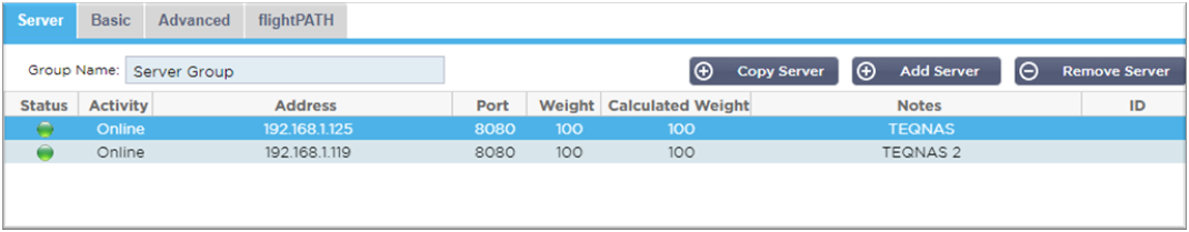
Add Server
· Select the appropriate VIP that you have previously defined.
· Click Add Server
· A new row will appear with the cursor blinking on the IP Address column

· Enter the IPv4 address of your server in dotted decimal notation. The Real Server can be on the same network as your Virtual Service, any directly attached local network, or any network that your ADC can route. Example "10.1.1.1".
· Tab to the Port column and enter the TCP/UDP port number for your server. The port number can be the same as the Virtual Service port number or another port number for Reverse Proxy Connectivity. The ADC will automatically translate to this number.
· Tab to the Notes section to add in any relevant detail for the server. Example: "IIS Web Server 1"
Group Name
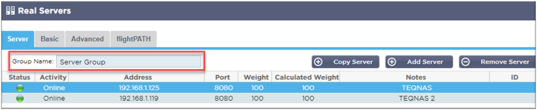
When you have added in the servers comprising the load-balanced set, you can also attach a Group Name. Once you have edited this field, the contents save without the need to press the Update button.
Real Server Status Lights
You can see the status of a Real Server by the light color in the Status column. See below:
|
LED
|
Meaning
|
|
l
|
Connected
|
|
£
|
Not Monitored
|
|
l
|
Draining
|
|
l
|
Offline
|
|
l
|
Standby
|
|
l
|
Not Connected
|
|
l
|
Finding Status
|
|
l
|
Not licensed or licensed Real Servers exceeded
|
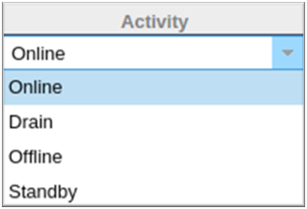
Activity
You can change the Activity of a Real Server at any time by using the dropdown menu. To do this, double-click on a Real Server row to place it into edit mode.
|
Option
|
Description
|
|
Online
|
All Real Servers assigned Online will receive traffic according to the load balancing policy set within the Basic tab.
|
|
Drain
|
All Real Servers assigned as Drain will continue to serve existing connections but will not accept any new connections. The Status light will flash green/blue while the drain is in process. Once the existing connections have closed naturally, the Real Servers will go offline, and the Status light will be solid blue. You can also view these connections by navigating to the Navigation > Monitor > Status section.
|
|
Offline
|
All Real Servers set as Offline will immediately be taken offline and will not receive any traffic.
|
|
Standby
|
All Real Servers set as Standby will remain offline until ALL the Online group servers fail their Server Health Monitor checks. Traffic is received by the Standby group as per the load balancing policy when this happens. If one server in the Online group passes the Server Health Monitor check, this Online server will receive all the traffic, and the Standby group will stop receiving traffic.
|
IP Address
This field is the IP address for your Real Server. Example "192.168.1.200".
Port
TCP or UDP port number that the Real Server is listening on for the service. Example "80" for Web Traffic.
Weight
This column will become editable when there is an appropriate Load Balancing Policy specified.
The default weight for a Real Server is 100, and you can enter values from 1-100. A value of 100 means maximum load, and 1 means minimum load.
An example for three servers may look something like this:
· Server 1 Weight = 100
· Server 2 Weight = 50
· Server 3 Weight = 50
If we consider the load balancing policy is set to Least Connections, and there are 200 total client connections;
· Server 1 will get 100 concurrent connections
· Server 2 will get 50 concurrent connections
· Server 3 will get 50 concurrent connections
If we were to use Round Robin as the load balancing method, which rotates requests through the load balanced server set, altering the weights affects how often the servers get chosen as the target.
If we believe the Fastest load balancing policy uses the shortest time taken to GET a response, adjusting the weights alters the bias similarly to Least Connections.
Calculated Weight
The Calculated Weight of each server can be viewed dynamically and is calculated automatically and is not editable. The field shows the actual weighting that ADC is using when considering manual weighting and load balancing policy.
Notes
Enter any particular notes helpful in describing the defined entry to the Notes field. Example "IIS Server1 – London DC".
ID
The ID field is used within the Cookie ID Load balancing Policy. The ID number placed here is used to identify
Basic
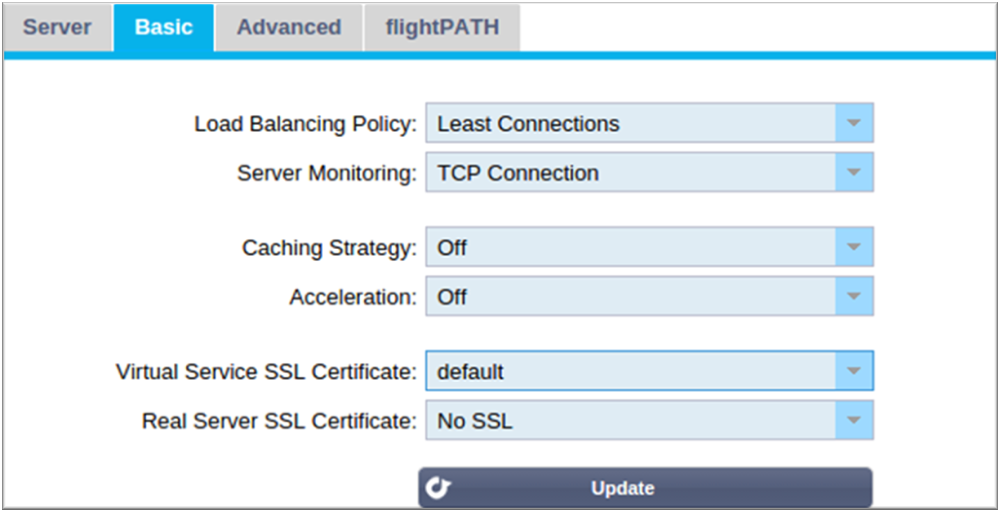
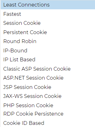
Load Balancing Policy
The dropdown list shows you the currently supported load balancing policies available for use. A list of load-balancing policies, together with an explanation, is below.
|
Option
|
Description
|
|
Fastest
|
The Fastest load balancing policy automatically calculates the response time for all requests per server smoothed over time. The Calculated Weight column contains the automatically calculated value. Manual entry is only possible when using this load balancing policy.
|
|
Round Robin
|
Round Robin is commonly used in firewalls and basic load balancers and is the simplest method. Each Real Server receives a new request in sequence. This method is only proper when you need to load balance requests to servers evenly; an example would be look-up web servers. However, when you need to load balance based on application load or the server load, or even ensure that you use the same server for the session, the Round Robin method is inappropriate.
|
|
Least Connections
|
The load balancer will keep track of the number of current connections to each Real Server. The Real Server with the least amount of connections receives the subsequent new request.
|
|
IP Bound
Layer 3 Session Affinity/Persistence
|
In this mode, the client's IP address forms the basis to select which Real Server will receive the request. This action provides persistence. HTTP and Layer 4 protocols can use this mode. This method is helpful for internal networks where the network topology is known, and you can be confident that there are no "super proxies" upstream. With Layer 4 and proxies, all the requests can look as if they are coming from one client, and as such, the load would not be even. With HTTP, the header (X-Forwarder—For) information is used when present to cope with proxies.
|
|
IP List Based
Layer 3 Session Affinity/Persistence
|
The connection to the Real Server initiates using "Least connections" then, session affinity is achieved based on the client's IP address. A list is maintained for 2 hours by default, but this can be changed using a jetPACK.
|
|
Session Cookie
Layer 7 Session Affinity/Persistence
|
This mode is the most popular persistence method for HTTP load balancing. In this mode, the ADC uses IP list-based load balancing for each first request. It inserts a cookie into the headers of the first HTTP response. After that, the ADC uses the client cookie to route traffic to the same back-end server. This cookie is used for persistence when the client needs to go to the same back-end server each time. The cookie expires once the session is closed.
|
|
Persistent Cookie
Layer 7 Session Affinity/Persistence
|
The IP list-based load balancing mode is used for each first request. The ADC inserts a cookie into the headers of the first HTTP response. After that, the ADC uses the client cookie to route traffic to the same back-end server. This cookie is used for persistence when the client must go to the same back-end server each time. The cookie will expire after 2 hours, and the connection will be load balanced according to an IP List Based algorithm. This expiry time is configurable using a jetPACK.
|
|
Session Cookie - Classic ASP Session Cookie
|
Active Server Pages (ASP) is a Microsoft server-side technology. With this option selected, the ADC will maintain session persistence to the same server if an ASP cookie is detected and found in its known cookies list. On detection of a new ASP cookie, it will be load balanced using the Least Connections algorithm.
|
|
Session Cookie - ASP.NET Session Cookie
|
This mode applies to ASP.net. With this mode selected, the ADC will maintain session persistence to the same server if an ASP.NET cookie is detected and found in its list of known cookies. On detection of a new ASP cookie, it will be load balanced using the Least Connections algorithm.
|
|
Session Cookie - JSP Session Cookie
|
Java Server Pages (JSP) is an Oracle server-side technology. With this mode selected, the ADC will maintain session persistence to the same server if a JSP cookie is detected and found in its known cookies list. On detection of a new JSP cookie, it will be load balanced using the Least Connections algorithm.
|
|
Session Cookie - JAX-WS Session Cookie
|
Java web services (JAX-WS) is an Oracle server-side technology. With this mode selected, the ADC will maintain session persistence to the same server if a JAX-WS cookie is detected and found in its list of known cookies. On detection of a new JAX-WS cookie, it will load balanced using the Least Connections algorithm.
|
|
Session Cookie - PHP Session Cookie
|
Personal Home Page (PHP) is an open-source server-side technology. With this mode selected, the ADC will maintain session persistence to the same server when a PHP cookie is detected.
|
|
Session Cookie - RDP Cookie Persistence
|
This load balancing method uses the Microsoft-created RDP Cookie based on username/domain to provide persistence to a server. The advantage of this method means maintaining a connection to a server is possible even if the IP address of the client changes.
|
|
Cookie-ID Based
|
A new method very much like "PhpCookieBased" and other load-balancing methods, but using CookieIDBased and cookie RegEx h=[^;]+
This method will use the value set in the Real Server’s notes field "ID=X;" as the cookie value to identify the server. This, therefore, means it is a similar methodology as CookieListBased but uses a different cookie name and stores a unique cookie value, not the scrambled IP, but the ID from the Real Server (read in at load-time.)
The Default value is CookieIDName="h"; however, if there is an override value in the virtual server’s advanced settings configuration, use this instead. NOTE: We overwrite the cookie expression above to replace h= with the new value if this value is set.
The last bit is that if an unknown cookie value arrives and matches one of the Real Server IDs, it should select that server; otherwise, use the next method (delegate.)
|
|
Shared IP List Based
|
This service type is only available when the Connectivity Mode is set to Gateway or Direct Server Return. It has been primarily added for support with VMware load balancing.
|
Server Monitoring
Your ADC contains six standard Real Server Monitoring methods listed below.
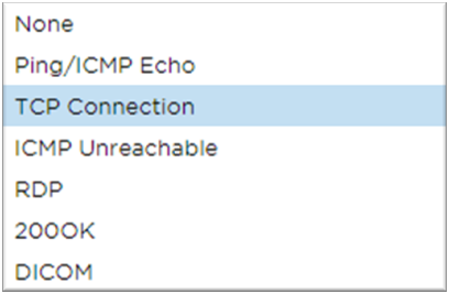
Choose the monitoring method you wish to apply to the Virtual Service (VIP).
It is essential to choose the right monitor for the service. For example, if the Real Server is an RDP server, a 200OK monitor is not relevant. If you are unsure which monitor to choose, the default TCP Connection is an excellent place to start.
You can choose multiple monitors by clicking each monitor you wish to apply to the service in turn. The selected monitors execute in the order you select them; hence start with monitors of the lower layers first. For example, setting monitors Ping/ICMP Echo, TCP Connection, and 200OK will display in the Dashboard Events like the image below:
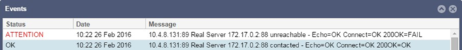
We can see that Layer 3 Ping and Layer 4 TCP Connect has succeeded if we look at the top line, but Layer 7 200OK has failed. These monitoring results provide enough information to indicate that routing is OK and there is a service running on the relevant port, but the website is not responding correctly to the page requested. It's now time to look at the webserver and the Library > Real Server Monitor section to see the details of the failing monitor.
|
Option
|
Description
|
|
None
|
In this mode, the Real Server is not monitored and is always up and running correctly. The None setting is helpful for situations where monitoring upsets a server and for services that should not join in the fail-over action of the ADC. It is a route to host unreliable or legacy systems that are not primary to H/A operations. Use this monitoring method with any service type.
|
|
Ping/ICMP Echo
|
In this mode, the ADC sends an ICMP echo request to the IP of the content server. If a valid echo response is received, the ADC deems the Real Server up and running, and traffic throughput to the server continues. It will also keep the service available on a H/A pair. This monitoring method is usable with any service type.
|
|
TCP Connection
|
A TCP connection is made to the Real Server and immediately broken without sending any data in this mode. If the connection succeeds, the ADC deems the Real Server to be up and running. This monitoring method is usable with any service type, and UDP services are currently not appropriate for TCP Connection monitoring.
|
|
ICMP Unreachable
|
The ADC will send a UDP health check to the server and mark the Real Server as unavailable if it receives an ICMP port unreachable message. This method can be helpful when you need to check if a UDP service port is available on a server, such as DNS port 53.
|
|
RDP
|
In this mode, a TCP connection initializes as explained in the ICMP Unreachable method. After the connection initializes, a Layer 7 RDP connection is requested. If the link is confirmed, the ADC deems the Real Server to be up and running. This monitoring method is usable with any Microsoft terminal server.
|
|
200 OK
|
In this method, a TCP connection initializes to the Real Server. After the connection succeeds, the ADC sends the Real Server an HTTP request. An HTTP response is waited for and checked for the "200 OK" response code. The ADC deems the Real Server up and running if the "200 OK" response code is received. If the ADC does not receive a "200 OK" response code for any reason, including timeouts, failure to connect, and other reasons, the ADC marks the Real Server unavailable. This monitoring method is only valid for use with HTTP and accelerated HTTP service types. If a Layer 4 Service type is used for an HTTP server, it is useable if SSL is not in use on the Real Server or handled appropriately by the "Content SSL" facility.
|
|
DICOM
|
A TCP connection initializes to the Real Server in DICOM mode, and an Echoscu "Associate Request" is made to the Real Server on connection. A conversation that includes an "Associate Accept" from the content server, a transfer of a small amount of data followed by a "Release Request," then "Release Response" successfully concludes the monitor. If the monitor does not complete successfully, then the Real Server is regarded as down for any reason.
|
|
User Defined
|
Any monitor configured in the Real Server Monitoring section will appear in the list.
|
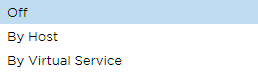
Caching Strategy
By default, the Caching Strategy is disabled and set as Off. If your service type is HTTP, then you can apply two types of Caching Strategy.
Please refer to the Configure Cache page to configure detailed cache settings. Note that when caching is applied to a VIP with the Accelerated "HTTP" service type, compressed objects are not cached.
|
Option
|
Description
|
|
By Host
|
Caching per host is based on application per hostname. A separate Cache will exist for each domain/hostname. This mode is ideal for web servers that can serve multiple websites depending on the domain.
|
|
By Virtual Service
|
Caching per virtual service is available when you choose this option. Only one Cache will exist for all domain/hostnames that pass through the virtual service. This option is a specialist setting for use with multiple clones of a single site.
|
Acceleration
|
Option
|
Description
|
|
Off
|
Turn compression off for the Virtual Service
|
|
Compression
|
When selected, this option turns on the compression for the selected Virtual Service. The ADC dynamically compresses the data stream to the client upon request. This process only applies to objects that contain the content-encoding: gzip header. Example content includes HTML, CSS, or Javascript. You can also exclude certain content types using the Global Exclusions section.
|
Note: If the object is cacheable, the ADC will store a compressed version and serve this statically (from memory) until the content expires and is re-validated.
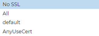
Virtual Service SSL Certificate (Encryption between Client and the ADC)
By default, the setting is No SSL. If your service type is "HTTP" or "Layer4 TCP", you can select a certificate from the dropdown to apply to the Virtual Service. Certificates that have been created or imported will appear in this list. You may highlight multiple certificates to apply to a service. This operation will automatically enable the SNI extension to allow a certificate based on the "Domain Name" requested by the client.
Server Name Indication
This option is an extension to the TLS networking protocol using which the client indicates what hostname it is attempting to connect to at the start of the handshaking process. This setting allows the ADC to present multiple certificates on the same virtual IP address and TCP port.
|
Option
|
Description
|
|
No SSL
|
Traffic from the source to the ADC is not encrypted.
|
|
All
|
Loads all available certificates for use
|
|
Default
|
This option results in applying a locally created certificate called "Default" to the browser side of the channel. Use this option to test SSL when one hasn't been created or imported.
|
|
AnyUseCert
|
Use any certificate present on the ADC that the user has uploaded or generated
|
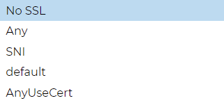
Real Server SSL Certificate (Encryption between the ADC and Real Server)
The default setting for this option is No SSL. If your server requires an encrypted connection, this value must be anything other than No SSL. Certificates that have been created or imported will appear in this list.
|
Option
|
Description
|
|
No SSL
|
Traffic from the ADC to the Real Server is not encrypted. The selection of a certificate on the browser side means "No SSL" can be chosen client-side to provide what is known as "SSL Offload."
|
|
Any
|
The ADC acts as a client and will accept any certificate the Real Server presents. Traffic from the ADC to the Real Server is encrypted when this option is selected. Use the "Any" option when a certificate is specified on the Virtual Service side, providing what is known as "SSL Bridging" or "SSL Re-Encryption."
|
|
SNI
|
The ADC acts as a client and will accept any certificate the Real Server presents. Traffic from the ADC to the Real Server is encrypted if this is selected. Use the "Any" option when a certificate is specified on the Virtual Service side, providing what is known as "SSL Bridging" or "SSL Re-Encryption." Choose this option to enable SNI on the server-side.
|
|
AnyUseCert
|
Any certificates that you have generated or imported into the ADC appear here.
|
Advanced
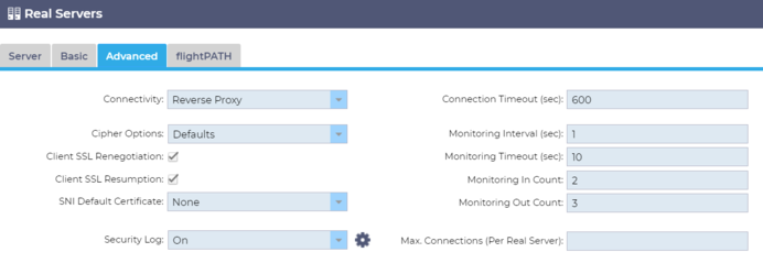
Connectivity
Your Virtual Service is configurable with different types of connectivity. Please select the connectivity mode to apply to the service.
|
Option
|
Description
|
|
Reverse Proxy
|
Reverse Proxy is the default value and works at Layer7 with compression and caching. And at Layer4 without caching or compression. In this mode, your ADC acts as a reverse proxy and becomes the source address seen by the Real Servers.
|
|
Direct Server Return
|
Direct Server Return or DSR as it's widely known (DR – Direct Routing in some circles) allows the server behind the load balancer to respond directly to the client bypassing the ADC on the response. DSR is only suitable for use with Layer 4 load balancing. Therefore, Caching and Compression are not available with this option chosen.
This mode can only be used with TCP, UDP, and TCP/UDP service types.
Layer 7 load balancing does not work with this DSR. Also, there is no persistence support other than IP List Based. SSL/TLS load balancing with this method is not ideal as Source IP persistence support is the only type available. DSR also requires Real Server changes to be done. Please refer to the Real Server Changes section.
|
|
Gateway
|
Gateway mode allows you to route all traffic through the ADC, allowing the Real Servers to be routed via the ADC to other networks via the ADC virtual machines or hardware interfaces. Using the device as a gateway device for Real Servers is ideal when running in multi-interface mode.
Layer 7 load balancing with this method does not work as there is no persistence support other than IP List Based. This method requires that the Real Server sets its default gateway to the ADC's local interface address (eth0, eth1, etc.). Please refer to the Real Server Changes section.
Please note that Gateway mode does not support failover in a cluster environment.
|
Cipher Options
Ciphers form the basis of SSL cryptography and are extremely important for successful and secure web content and application delivery.
The ADC contains a built-in set of default Ciphers, comprising the most up-to-date and secure ones available for use.
There are occasions when the user wishes to announce the availability of a particular set of Ciphers, and the ADC allows the creation of such Ciphers through user-authored jetPACKS. jetPACKS written by users can be imported into the ADC through Configuration > Software, then made available for choosing using the Cipher Options menu.
Cipher Options are specific to each VIP, delivering high flexibility and security.
For more information on Cipher Options, please see: Cipher Options
Client SSL Renegotiation
Tick this box if you wish to allow client-initiated SSL renegotiation. Disable client SSL renegotiation to prevent any possible DDOS attacks against the SSL Layer by un-ticking this option.
Client SSL Resumption
Tick this box if you wish to enable SSL Resumption Server sessions added to the session cache. When a client proposes re-use of a session, the server will try to reuse the session if found. If Resumption is un-checked, no session caching for the client or server takes place.
SNI Default Certificate
During an SSL connection with the Client-side SNI enabled, if the requested domain does not match any of the certificates assigned to the service, the ADC will present the SNI Default Certificate. The default setting for this is None which would effectively drop the connection should there be no exact match. Choose any of the certificates installed from the dropdown to present should an exact SSL certificate match fail.
Security Log
'On' is the default value and is on a per-service basis, enabling the service of logging authentication information to the W3C logs. Clicking the Cog icon will take you to the System > Logging page, where you can check the settings of the W3C logging.
Connection Timeout
The default connection timeout is 600 seconds or 10 minutes. This setting will adjust the time for the connection to timeout out upon no activity. Reduce this for short-lived stateless web traffic, which is typically 90s or less. Increase this figure for stateful connections such as RDP to something like 7200 seconds (2 hours) or more, depending on your infrastructure. The RDP timeout example means that if a user has a period of inactivity of 2 hours or less, the connections will remain open.
Monitoring Settings
These settings relate to the Real Server Monitors in the Basic tab. There are global entries in the configuration to count the number of successful or failed monitors before a server's status is marked online or failed.
Interval
The interval is the time in seconds between monitors. The default interval is 1second. While 1s is acceptable for most applications, it may be beneficial to increase this for others or during testing.
Monitoring Timeout
The timeout value is when the ADC will wait for a server to respond to a connection request. The default value is 2s. Increase this value for busy servers.
Monitoring In Count
The default value for this setting is 2. The value of 2 indicates that the Real Server must pass two successful health monitor checks before it comes online. Increasing this figure will increase the probability that the server can serve traffic but will take longer to come into service depending on the interval. Decreasing this value will bring your server into service sooner.
Monitoring Out Count
The default value for this setting is 3, meaning that the Real Server monitor must fail three times before the ADC will stop sending traffic to the server, and it is marked RED and Unreachable. Increasing this figure will result in better and more reliable service at the expense of the time it takes the ADC to stop sending traffic to this server.
Switch To Offline On Failure
When this is checked, the Real Servers that fail their health check are placed offline and can only be set online manually.
Max. Connections
Limits the number of simultaneous Real Server connections and is set per service. For example, if you configure this to 1000 and have two Real Servers, the ADC limits each Real Server to 1000 concurrent connections. You may also choose to present a "Server too busy" page once this limit is reached on all servers, helping users understand why any non-response or delay has occurred. Leave this blank for unlimited connections. What you set here depends on your system resources.
flightPATH
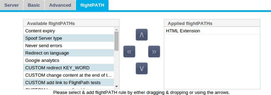
flightPATH is a system designed by Edgenexus and exclusively available within the ADC. Unlike other vendors' rules-based engines, flightPATH does not operate through a command line or script entry console. Instead, it uses a GUI to select the different parameters, conditions, and actions to perform to achieve what they need. These features make flightPATH extremely powerful and allow network administrators to manipulate HTTPS traffic in highly effective ways.
flightPATH is only available for use with HTTPS connections, and this section is not visible when the Virtual Service Type is not HTTP.
You can see from the image above; there is a list of available rules on the left and the rules applied to the virtual service on the right.
Add an available rule by dragging and dropping the rule from the left side to the right or highlighting a rule and clicking the right arrow to move it to the right side.
The order for execution is essential and starts with the top rule executed first. To change the order of execution, highlight the rule and move up and down using the arrows.
To remove a rule, drag and drop it back to the rule inventory on the left or highlight the rule and click the left arrow.
You can add, remove and edit flightPATH rules in the Configure flightPATH section of this guide.