
Network
The Network section within the Library allows the configuration of the ADC’s network interfaces and their behavior.
Basic Setup
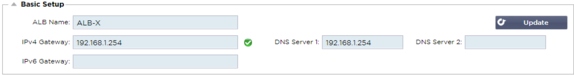
ALB Name
Specify a name for your ADC appliance. Please note that this cannot be changed if there is more than one member in the cluster. Please see the section on Clustering.
IPv4 Gateway
Specify the IPv4 Gateway address. This address will need to be in the same subnet as an existing adapter. If you add in Gateway incorrectly, you will see a White Cross in a red circle. When you add a correct gateway, you will see a green success banner at the bottom of the page and a white tick in a green circle next to the IP address.
IPv6 Gateway
Specify the IPv6 Gateway address. This address will need to be in the same subnet as an existing adapter. If you add in Gateway incorrectly, you will see a White Cross in a red circle. When you add a correct gateway, you will see a green success banner at the bottom of the page and a white tick in a green circle next to the IP address.
DNS Server 1 & DNS Server 2
Add in the IPv4 address of your first and second (optional) DNS server.
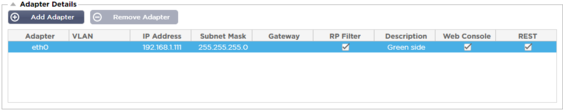
Adapter Details
This section of the Network panel shows the network interfaces that are installed in your ADC appliance. You can add and remove adapters as needed.
|
Column
|
Description
|
|
Adapter
|
This column displays the physical adapters installed on your appliance. Choose an adapter from the list of available adapters by clicking on it – a double-click will place the listing line into edit mode.
|
|
VLAN
|
Double click to add the VLAN ID for the adapter. A VLAN is a Virtual Local Area Network which creates a distinct broadcast domain. A VLAN has the same attributes as physical LAN but it allows for end stations to be grouped together more easily if they are not on the same network switch
|
|
IP Address
|
Double click to add the IP address associated with the adapter interface. You can add multiple IP addresses to the same interface. This should be an IPv4 32-bit number in quad dotted decimal notation. Example 192.168.101.2
|
|
Subnet Mask
|
Double click to add the subnet mask assigned to the adapter interface. This should be an IPv4 32-bit number in quad dotted decimal notation. Example 255.255.255.0
|
|
Gateway
|
Add a gateway for the interface. When this is added the ADC will set-up a simple policy that will allow connections initiated from this interface to be returned via this interface to the gateway router specified. This allows the ADC to be installed in more complex networking environments without the trouble of manually configuring complex policy based routing.
|
|
Description
|
Double click to add a description for your adapter. Example Public Interface.
Note: The ADC will automatically name the first interface Green Side, the second interface Red Side and the third interface Side 3 etc.
Please feel free to change these naming conventions to your own choice.
|
|
Web Console
|
Double click the column then tick the box to assign the interface as the management address for the Graphical User Interface Web Console. Please be very careful when changing the interface that Web Console will listen on. You will need to have the correct routing set up or be in the same subnet as the new interface in order to reach the Web Console after the change. The only way to change this back is to access the command line and issue the set greenside command. This will delete all interfaces except for eth0.
|
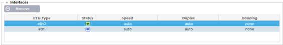
Interfaces
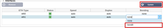
The Interfaces section within the Network panel allows the configuration of certain elements pertaining to the network interface. You can also remove a network interface from the listing by clicking the Remove button. When using a virtual appliance, the interfaces you see here are limited by the underlying virtualization framework.
|
Column
|
Description
| ||||||||
|
ETH Type
|
This value indicates the internal OS reference to the network interface. This field cannot be customized. Values begin with ETH0 and continue in sequence depending on the number of network interfaces.
| ||||||||
|
Status
|
This graphical indication shows the current status of the network interface. A Green status shows that the interface is connected and up. Other status indicators are shown below.
| ||||||||
|
Speed
|
By default, this value is set to auto-negotiate the speed. But you can change the network speed of the interface to any value available in the drop-down (10/100/1000/AUTO).
| ||||||||
|
Duplex
|
The value of this field is customizable, and you can choose between Auto (default), Full-Duplex, and Half-Duplex.
| ||||||||
|
Bonding
|
You can choose one of the bonding types that you have defined. See the section on Bonding for more details.
|
Bonding
Many names are used to title network interface bonding: Port Trunking, Channel Bonding, Link Aggregation, NIC teaming, and others. Bonding combines or aggregates multiple network connections into a single channel bonded interface. Bonding allows two or more network interfaces to act as one, increase throughput, and provide redundancy or failover.
The ADC’s kernel has a built-in Bonding driver for aggregating multiple physical network interfaces into a single logical interface (for example, aggregating eth0 and eth1 into bond0). For each bonded interface, you can define the mode and the link monitoring options. There are seven different mode options, each providing specific load balancing and fault tolerance characteristics. These are shown in the image below.
Note: Bonding can only be configured for hardware-based ADC appliances.
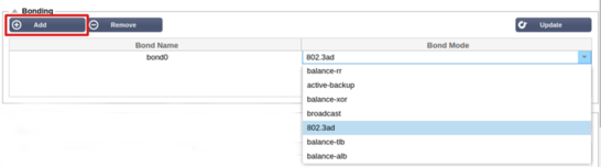
Creating a Bonding profile
· Click on Add button to add a new Bond
· Provide a name for the bonding configuration
· Choose which bonding mode you wish to use
Then from the Interfaces section, select the Bonding mode you wish to use from the Bond drop-down field for the network interface.
In the example below, eth0, eth1, and eth2 are now part of bond0. While Eth0 remains on its own as the management interface.
Bonding Modes
|
Bonding Mode
|
Description
|
|
balance-rr:
|
Packets are sequentially transmitted/received through each interface one by one.
|
|
active-backup:
|
In this mode, one interface will be active, and the second interface will be on standby. This secondary interface only becomes active if the active connection on the first interface fails.
|
|
balance-xor:
|
Transmits based on source MAC address XOR’d with destination MAC address. This option selects the same slave for each destination Mac address.
|
|
broadcast:
|
This mode will transmit all data on all slave interfaces.
|
|
802.3ad:
|
Creates aggregation groups that share the same speed and duplex settings and utilizes all the slaves in the active aggregator following the 802.3ad specification.
|
|
balance-tlb:
|
The Adaptive transmit load balancing bonding mode: Provides channel bonding that does not require any special switch support. The outgoing traffic is distributed according to the current load (computed relative to the speed) on each slave. The current slave receives incoming traffic. If the receiving slave fails, another slave takes over the MAC address of the failed receiving slave.
|
|
balance-alb:
|
The Adaptive load balancing bonding mode: also includes balance-tlb plus receive load balancing (rlb) for IPV4 traffic and does not require any special switch support. The receive load balancing is achieved by ARP negotiation. The bonding driver intercepts the ARP Replies sent by the local system on their way out and overwrites the source hardware address with the unique hardware address of one of the slaves in the bond, such that different peers use different hardware addresses for the server.
|
Static Route
There will be times when you need to create static routes for specific subnets within your network. The ADC provides you with the ability to do this using the Static Routes module.
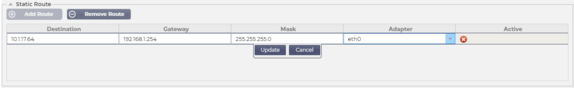
Adding a Static Route
· Click the Add Route button
· Fill in the field using the details in the table below as guidance.
· Click the Update button when done.
|
Field
|
Description
|
|
Destination
|
Enter the destination network address in decimal dotted notation. Example 123.123.123.5
|
|
Gateway
|
Enter the gateway IPv4 address in decimal dotted notation. Example 10.4.8.1
|
|
Mask
|
Enter the destination subnet mask in decimal dotted notation. Example 255.255.255.0
|
|
Adapter
|
Enter the adapter that the gateway can be reached on. Example eth1.
|
|
Active
|
A green tick box will indicate that the gateway can be reached. A red cross will indicate that the gateway cannot be reached on that interface. Please make sure you have set up an interface and IP address on the same network as the gateway
|
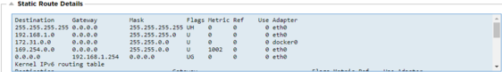
Static Route Details
This section will provide information about all the routes configured on the ADC.
Advanced Network Settings
What is Nagle?
Nagle's algorithm improves the efficiency of TCP/IP networks by reducing the number of packets that need to be sent over the network. See Wikipedia Article on Nagle
Server Nagle
Tick this box to enable the Server Nagle setting. The Server Nagle is a means of improving the efficiency of TCP/IP networks by reducing the number of packets that need to be sent over the network. This setting is applied to the Server side of the transaction. Care must be taken with the server settings as Nagle and delayed ACK may severely impact performance.
Client Nagle
Tick the box to enable the Client Nagle setting. As above but applied to the Client side of the transaction.
SNAT
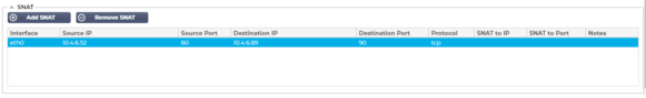
SNAT stands for Source Network Address Translation, and different vendors have slight variations in the implementation of SNAT. A simple explanation of the EdgeADC SNAT would be as follows.
Under normal circumstances, inbound requests would be directed to the VIP that would see the source IP of the request. So, for example, if a browser endpoint had an IP address of 81.71.61.51, this would be visible to the VIP.
When SNAT is in force, the original source IP of the request will be hidden from the VIP, and instead, it will see the IP address as provided in the SNAT rule. Thus, SNAT can be used in Layer 4 and Layer 7 load balancing modes.
|
Field
|
Description
|
|
Source IP
|
The Source IP address is optional, and it can be either a network IP address (with /mask) or a plain IP address. The mask can be either a network mask or a plain number, specifying the number of 1’s at the left side of the network mask. Thus, a mask of /24 is equivalent to 255.255.255.0.
|
|
Destination IP
|
The Destination IP address is optional, and it can be either a network IP address (with /mask) or a plain IP address. The mask can be either a network mask or a plain number, specifying the number of 1’s at the left side of the network mask. Thus, a mask of /24 is equivalent to 255.255.255.0.
|
|
Source Port
|
The source port is optional, it can be a single number, in which case it specifies only that port, or it can include a colon, which specifies a range of ports. Examples: 80 or 5900:5905.
|
|
Destination Port
|
The destination port is optional, it can be a single number, in which case it specifies only that port, or it can include a colon, which specifies a range of ports. Examples: 80 or 5900:5905.
|
|
Protocol
|
You can choose whether to use SNAT on a single protocol or all the protocols. We suggest being specific to be more precise.
|
|
SNAT to IP
|
SNAT to IP is a mandatory IP address or a range of IP addresses. Examples: 10.0.0.1 or 10.0.0.1-10.0.0.3.
|
|
SNAT to Port
|
The SNAT to Port is optional, it can be a single number, in which case it specifies only that port, or it can include a dash, which specifies a range of ports. Examples: 80 or 5900-5905.
|
|
Notes
|
Use this to put a friendly name to remind yourself why the rules exist. This is also useful for debugging in the Syslog.
|